

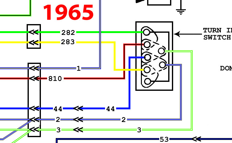
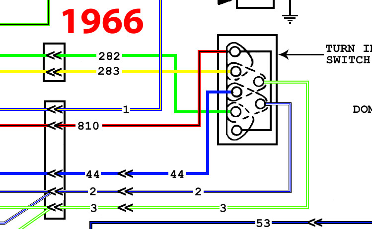
The main harness circuits going into the connector at the base of the steering column for the turn signal switch are identical...but the two diagrams seem to show a different destination for the circuits up inside the turn signal switch itself, after the connector.
So this made me wonder if this is another Ford engineering SNAFU that got past the proofreader or what, so I started doing some digging in the MPC to see if there was a different switch used between the '65 and '66 models. Here's what I found:
C0DZ-13341-A (less mounting plate)
61-62 F100/250 2WD
C2TZ-13341-D
61-66 F350, 61-65 F100/250 4WD, 66 F250 4WD
C3TZ-13341-B
63-64 F100/250 2WD
C9TZ-13341-C
65 F100/250 2WD, 66 F100 2WD/4WD, 66 F250 2WD, 67-69 F100/350 "Before Ser. G30,001"
As you can see, there were actually four different part numbers used for turn signal switches used in the Slicks era. The C0DZ-A switch came without a mounting plate, which was replaced with the C3TZ-B piece which included the mounting plate...which means it could also replace the earlier version, meaning there are actually only three different switches used.
So in a nutshell, the F350 and 4WD up through '66 used one switch, '61-'64 2WDs used a second one, and the third was used on '65-'66 2WDs and '66 4WDs.
Since the question here is why is the turn signal portion of the diagram different between the '65 and '66 diagram, this PN research seems to show that the turn signal portion of the wiring diagram is irrelevant, since the diagram is labeled "F100, F250 6 & 8 Cyl." and doesn't show actual application, meaning that essentially the wiring harnesses between the '65 and '66 trucks are identical. So which one is correct...and does it even matter?
Thoughts? I'm thinking about just editing the '66 colorized diagram I have to label it as '65 and '66 and using for both. Does anyone see any potential problems with that, or should I just colorize the '65 diagram as printed? (It wouldn't take more than 5 minutes to do, literally....since I could just edit the '66 diagram to reflect the minor differences in the TSS portion in the '65 diagram.)