Re: '65 F100 SWB - yes another Crown Vic swap
Posted: February 28, 2018, 7:19 am
Final Assembly (part 15)
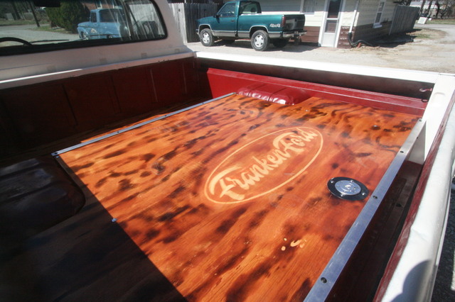
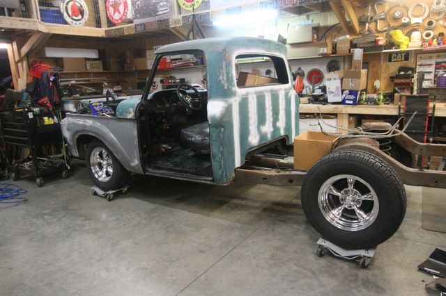
So with the framework for the raised bed welded into place it was time to start cutting the wood pieces that will be the bed floor, all of the original bed will get covered in wood even the area right behind the cab, that will give it a cohesive look, the truck will again like the uni get a bed cover at some point so it will be protected.
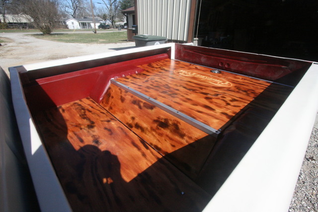
Once all the pieces were cut we used black oil based paint to cover the bottom of the wood, a couple coats covering the surface and edges will protect and seal it for a lot of years, the top side will again have a coating applied that will let the plywood accept stain after being distressed, then several coats of polyurethane.


All of the mounting is done with 1/4 x 3" carriage bolts, and all the holes were drilled before any painting, so those holes will get a little sealer in them...hopefully.
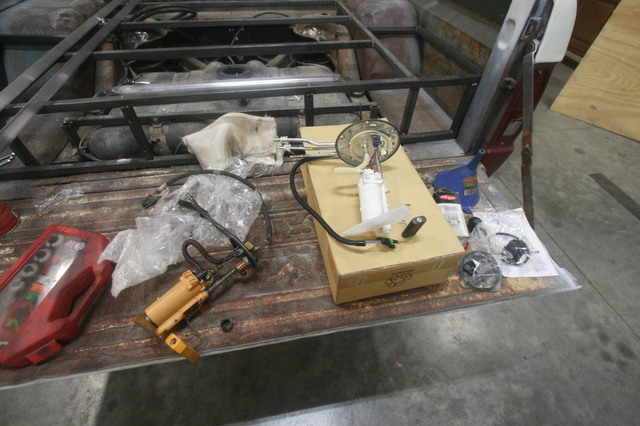
The fuel filler will be in the bed floor, we bought a flush cap flange mounted aluminum filler for a marine application that should work fine, it will be mounted close to the tail gate in the center of the rear portion of the bed floor, it makes for a straight shot down then 90 degrees into the fuel tank and will be raised about 6" above the tank inlet so should be safe from fuel sloshing out when the tank is full.
I still need to replace the fuel pump / sending unit before the floor goes in the bed, I have the new unit that has been sitting on the bench for over a month it just needs to be installed then we can close up the bed floor, of course we are making the floor so it is removable if the pump had to be replaced again and all of the bed structure is attached to the bed so the entire bed could be removed if need be, actually after it is complete you could disconnect the fuel filler, and remove 4 bolts and the bed will lift off although a lot heaver then it was when we put it on the chassis...lol
------
While I was working on building the framework my wife was working on the dash instrument cluster bezel painting it to match the dash, then creating a mask for the inside of the polycarbonate sheet that we are using to cover the Roadmaster instrument cluster. I have previously totally disassembled the cluster and cut the plastic housing down to the smallest possible size without damaging the cluster. It is still large for the slicks dash opening but does fit now without having to be angled.
After all of her work had dried over night I installed it in the slicks dash, I have to say it looks way better than I ever thought it would and gives the interior / dash a semi modern look while keeping the slicks dash original.
What do you folks think...?

This is a "proof of concept" to me, and it is a success, the other trucks will get the same treatment of reusing the donor instrument cluster in the same fashion, the Crown Vic's cluster is smaller in height so will be much easier to retro fit it into the slicks dash without all the cutting and hacking I had to do to the RM cluster, I don't think it looks bad at all compared to other cluster/dash mods I've seen on the internet, it looks somewhat factory or like it was suppose to be.
There are a few issues, because of the size of the RM cluster the cropping (blacked out) of the polycarbonate hides a little of the top of the speedo numbers, hides the PRNDL at the bottom of the cluster (not used anyway), and shadows a couple of the warning lights on each side of the cluster....not a big deal to me, if you look at the picture from Drew Bros that I posted in another post you will see their cropping does the same thing but maybe a little less than ours does...everything that is important to the driver is in plain view which is what I was going for. The picture from the side actually makes it look like more is masked than actually is, I'll try to get a driver's perspective shot and post that in a future post but I think you folks get the idea.
This took a considerable amount of effort to accomplish, as I said earlier I totally disassembled the RM cluster to look at the circuit board and just how much could be safely cut away, in the end the best I could do was shrink its physical size down to the size of the circuit board, I used a small air saw to hack at the plastic housing till it was at its smallest size which removed all the mounts and tabs that held it in the RM dash and held the pieces of the cluster together.
Looking at the picture below, everything bigger than the circuit board had to be cut away....

And this picture should give you a idea of the physical size of the RM cluster in relation to the slicks bezel.

Since I needed to be able to service it in the future (replace lighting etc) I used "gaffers tape" to hold it all together, if you don't know what that is.....
https://www.amazon.com/Premium-Gaffer-G ... B00GZE3UJ8
Gaffers tape is one of the best inventions I've ever used, it is a cloth tape that is super sticky but removable, when removed it leaves no adhesive residue, it was prefect to use to hold the 3 sections of the RM cluster together after I cut all the tabs off. I also while disassembling the cluster had to remove the needles from the stepper motors to access the underside of the face, there are a lot of resources on the internet telling you how to successfully remove and reinstall them so I'll just say it's a area where you want to be careful.
In the slicks dash opening I had to cut out the old bracing that supported the pedal assembly that is spot welded to the top of the dash, I didn't remove all of it but cut off about half leaving the upper portion intact, I originally thought that the portion I left might be useful to support the back of the RM cluster but because it is angled down from the dash only the top of the cluster could be supported by it, the RM brake pedal assembly top portion is also kinda' in the way but in the end I didn't have to modify it at all and in fact after moving some of the wiring bundles around it supports one corner of the bottom of the cluster.

I really wanted to mount the cluster to the slicks bezel but it's not possible as far as I can see so they are two separate assemblies, because the RM cluster has to be tilted to go through the dash opening it can't be attached to the bezel, then the cluster can't be right up against the bezel because it would block the tabs in the dash that the screws holding the bezel to the dash go through and they won't clear the cluster ...the screws would go into the cluster. We'll see after it's on the road awhile how it fairs it's pretty tightly held in place but not totally secured like I'd want it to be....we'll see.
There probably is another way to do this that I'm missing, not real sure, I spent a considerable amount of time thinking about how to get it to fit through the slicks dash opening as a complete assembly, once it's attached to the bezel there is only a limited amount of movement you can make and none of it for me got it through the opening all in one piece.
One thing I did think about was gluing a couple pieces of plastic tubing to the sides of the RM cluster then using long machine screws like a 10-32 that would be threaded its entire length I could have went through the bezel and polycarbonate installed a washer and nut then made a couple tube spacers to fill the void between the bezel and the cluster (for the spacing away from the bezel) then going through those glued on tubes and a washer and nut could be installed from under the dash, but that 10-32 screw would have to be 4-5" long, it's not that that wouldn't work because if you could get enough bond gluing the tube to the cluster that it would support the weight and wiggling it around it would be just fine once installed, I may have to go back and do that, again we'll see what happens.
I'm thrilled at how it turned out even though it's kind of a "shadow box" look since the cluster sits back away from the bezel, but for a little bit of effort and a whole lot of thinking we saved probably $800 that aftermarket OBD2 gauges would have cost us and they might have looked better, but $800 dollars better? Granted we are just building daily drivers not show vehicles but everyone who stopped by over the weekend and saw the cluster in the dash was impressed.
----
After the bed floor the next item is to build a couple speaker cabinets to fit behind the seat and the console to house the radio, this truck will again get a backup camera but unlike the uni it will be tied to the backup lights so it will automatically come on when the vehicle is backing up. Since the doors were cut for 6.5" speakers we will be putting new speakers in those openings along with a couple 6x9 speakers behind the seat. One of the things on the uni I really like is using a USB stick to house MP3s, one smallish stick plugged into the USB on the radio will house enough music for days and days of driving without ever listening to the same song twice.
Once the fuel filler is installed we can actually start driving the truck while we finish the other aspects of the build, because of where and how the fuel filler is in the tank we have been hesitant to drive it since fuel can slosh out the filler which makes for a unsafe situation, but we will have that taken care of next weekend...hopefully.
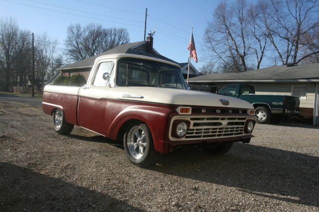
Then mostly what I have left is the front bumper, I need to fabricate mounts like I did on the uni that I can weld to the RM frame but will allow us to remove the bumper, the wife needs to paint the doors with the UGH-LAY logo, and we need to distress the paint, as you can see we are coming to the end of this build quickly.
----
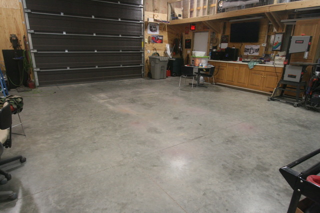
I've already spent a little spare time on the '62 flare side cab stripping out the inside of the dash and the driver's door, once the '65 is out of the shop I'll come up with a attack plan for the cab and bed, I need to time the removal of the '09 CV body so I can set the cab on it right away and the whole thing can be shoved over into the corner of the shop, we are getting into the time of year when my wife will be using the shop a lot so I need to make sure I'm not in her way.
Jon
So with the framework for the raised bed welded into place it was time to start cutting the wood pieces that will be the bed floor, all of the original bed will get covered in wood even the area right behind the cab, that will give it a cohesive look, the truck will again like the uni get a bed cover at some point so it will be protected.
Once all the pieces were cut we used black oil based paint to cover the bottom of the wood, a couple coats covering the surface and edges will protect and seal it for a lot of years, the top side will again have a coating applied that will let the plywood accept stain after being distressed, then several coats of polyurethane.
All of the mounting is done with 1/4 x 3" carriage bolts, and all the holes were drilled before any painting, so those holes will get a little sealer in them...hopefully.
The fuel filler will be in the bed floor, we bought a flush cap flange mounted aluminum filler for a marine application that should work fine, it will be mounted close to the tail gate in the center of the rear portion of the bed floor, it makes for a straight shot down then 90 degrees into the fuel tank and will be raised about 6" above the tank inlet so should be safe from fuel sloshing out when the tank is full.
I still need to replace the fuel pump / sending unit before the floor goes in the bed, I have the new unit that has been sitting on the bench for over a month it just needs to be installed then we can close up the bed floor, of course we are making the floor so it is removable if the pump had to be replaced again and all of the bed structure is attached to the bed so the entire bed could be removed if need be, actually after it is complete you could disconnect the fuel filler, and remove 4 bolts and the bed will lift off although a lot heaver then it was when we put it on the chassis...lol
------
While I was working on building the framework my wife was working on the dash instrument cluster bezel painting it to match the dash, then creating a mask for the inside of the polycarbonate sheet that we are using to cover the Roadmaster instrument cluster. I have previously totally disassembled the cluster and cut the plastic housing down to the smallest possible size without damaging the cluster. It is still large for the slicks dash opening but does fit now without having to be angled.
After all of her work had dried over night I installed it in the slicks dash, I have to say it looks way better than I ever thought it would and gives the interior / dash a semi modern look while keeping the slicks dash original.
What do you folks think...?
This is a "proof of concept" to me, and it is a success, the other trucks will get the same treatment of reusing the donor instrument cluster in the same fashion, the Crown Vic's cluster is smaller in height so will be much easier to retro fit it into the slicks dash without all the cutting and hacking I had to do to the RM cluster, I don't think it looks bad at all compared to other cluster/dash mods I've seen on the internet, it looks somewhat factory or like it was suppose to be.
There are a few issues, because of the size of the RM cluster the cropping (blacked out) of the polycarbonate hides a little of the top of the speedo numbers, hides the PRNDL at the bottom of the cluster (not used anyway), and shadows a couple of the warning lights on each side of the cluster....not a big deal to me, if you look at the picture from Drew Bros that I posted in another post you will see their cropping does the same thing but maybe a little less than ours does...everything that is important to the driver is in plain view which is what I was going for. The picture from the side actually makes it look like more is masked than actually is, I'll try to get a driver's perspective shot and post that in a future post but I think you folks get the idea.
This took a considerable amount of effort to accomplish, as I said earlier I totally disassembled the RM cluster to look at the circuit board and just how much could be safely cut away, in the end the best I could do was shrink its physical size down to the size of the circuit board, I used a small air saw to hack at the plastic housing till it was at its smallest size which removed all the mounts and tabs that held it in the RM dash and held the pieces of the cluster together.
Looking at the picture below, everything bigger than the circuit board had to be cut away....
And this picture should give you a idea of the physical size of the RM cluster in relation to the slicks bezel.
Since I needed to be able to service it in the future (replace lighting etc) I used "gaffers tape" to hold it all together, if you don't know what that is.....
https://www.amazon.com/Premium-Gaffer-G ... B00GZE3UJ8
Gaffers tape is one of the best inventions I've ever used, it is a cloth tape that is super sticky but removable, when removed it leaves no adhesive residue, it was prefect to use to hold the 3 sections of the RM cluster together after I cut all the tabs off. I also while disassembling the cluster had to remove the needles from the stepper motors to access the underside of the face, there are a lot of resources on the internet telling you how to successfully remove and reinstall them so I'll just say it's a area where you want to be careful.
In the slicks dash opening I had to cut out the old bracing that supported the pedal assembly that is spot welded to the top of the dash, I didn't remove all of it but cut off about half leaving the upper portion intact, I originally thought that the portion I left might be useful to support the back of the RM cluster but because it is angled down from the dash only the top of the cluster could be supported by it, the RM brake pedal assembly top portion is also kinda' in the way but in the end I didn't have to modify it at all and in fact after moving some of the wiring bundles around it supports one corner of the bottom of the cluster.
I really wanted to mount the cluster to the slicks bezel but it's not possible as far as I can see so they are two separate assemblies, because the RM cluster has to be tilted to go through the dash opening it can't be attached to the bezel, then the cluster can't be right up against the bezel because it would block the tabs in the dash that the screws holding the bezel to the dash go through and they won't clear the cluster ...the screws would go into the cluster. We'll see after it's on the road awhile how it fairs it's pretty tightly held in place but not totally secured like I'd want it to be....we'll see.
There probably is another way to do this that I'm missing, not real sure, I spent a considerable amount of time thinking about how to get it to fit through the slicks dash opening as a complete assembly, once it's attached to the bezel there is only a limited amount of movement you can make and none of it for me got it through the opening all in one piece.
One thing I did think about was gluing a couple pieces of plastic tubing to the sides of the RM cluster then using long machine screws like a 10-32 that would be threaded its entire length I could have went through the bezel and polycarbonate installed a washer and nut then made a couple tube spacers to fill the void between the bezel and the cluster (for the spacing away from the bezel) then going through those glued on tubes and a washer and nut could be installed from under the dash, but that 10-32 screw would have to be 4-5" long, it's not that that wouldn't work because if you could get enough bond gluing the tube to the cluster that it would support the weight and wiggling it around it would be just fine once installed, I may have to go back and do that, again we'll see what happens.
I'm thrilled at how it turned out even though it's kind of a "shadow box" look since the cluster sits back away from the bezel, but for a little bit of effort and a whole lot of thinking we saved probably $800 that aftermarket OBD2 gauges would have cost us and they might have looked better, but $800 dollars better? Granted we are just building daily drivers not show vehicles but everyone who stopped by over the weekend and saw the cluster in the dash was impressed.
----
After the bed floor the next item is to build a couple speaker cabinets to fit behind the seat and the console to house the radio, this truck will again get a backup camera but unlike the uni it will be tied to the backup lights so it will automatically come on when the vehicle is backing up. Since the doors were cut for 6.5" speakers we will be putting new speakers in those openings along with a couple 6x9 speakers behind the seat. One of the things on the uni I really like is using a USB stick to house MP3s, one smallish stick plugged into the USB on the radio will house enough music for days and days of driving without ever listening to the same song twice.
Once the fuel filler is installed we can actually start driving the truck while we finish the other aspects of the build, because of where and how the fuel filler is in the tank we have been hesitant to drive it since fuel can slosh out the filler which makes for a unsafe situation, but we will have that taken care of next weekend...hopefully.
Then mostly what I have left is the front bumper, I need to fabricate mounts like I did on the uni that I can weld to the RM frame but will allow us to remove the bumper, the wife needs to paint the doors with the UGH-LAY logo, and we need to distress the paint, as you can see we are coming to the end of this build quickly.
----
I've already spent a little spare time on the '62 flare side cab stripping out the inside of the dash and the driver's door, once the '65 is out of the shop I'll come up with a attack plan for the cab and bed, I need to time the removal of the '09 CV body so I can set the cab on it right away and the whole thing can be shoved over into the corner of the shop, we are getting into the time of year when my wife will be using the shop a lot so I need to make sure I'm not in her way.
Jon