Re: '65 F100 SWB - yes another Crown Vic swap
Posted: December 26, 2017, 8:15 am
This topic is about replacing the chassis - frame on a 1965 Ford F100 and swapping it with a 1996 Buick Roadmaster, this is a complete chassis swap including drive train and electrical, basically a body swap, keywords...... 1961 1962 1963 1964 1965 1966 Ford F-100 pick up unibody step side style side, Buick Roadmaster, Chassis, Frame, Swap, Crown Vic, complete frame swap, I'm adding this text to help with SEO (search engine optimization) so the thread - topic is more easily found from a google search.
-------
Mock up (part 4)
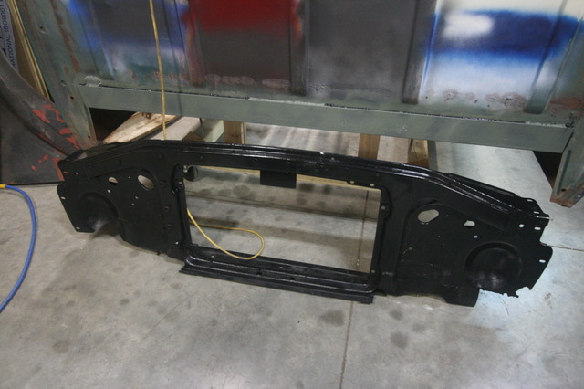
The radiator support or core support has the job of carrying all the weight of the front end sheet metal so it needs to be mounted to the frame securely but also needs a little bit of adjustment for the alignment of all the parts it is supporting. The original slick frame was a lot narrower than the RM so mounting points were going to be in different locations, there are a lot of different ways you could mount the radiator support to the RM frame but in my case since I had to cut out bad metal from the old support and replace that metal it just made sense to reinforce the area right above the RM frame that the radiator support spanned and use that area to mount the support to.

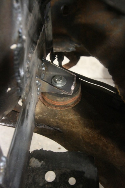
Once again I reused some of the body mounts from the CV as I did before mounting the cab, these mounts are molded rubber with a plastic center and use a steel insert to support the bottom of the mount and provide a tube for the bolt to pass through, I found the proper location in the frame and drilled my holes then cut a couple pieces of 2x2 tube at a 45 degree angle to make the mount that I would weld to the support.

I test fitted everything using multi-able levels to make sure everything was flat and level, then tacked the pieces of 2x2 to the core support.

Then tore it all back apart again and welded the mounts to the core support.


Then reassembled the front end again... this is what the mounts look like, they are on the engine side of the radiator support.

So with the radiator support mocked up I again removed it and gave it a coat of the rust converter and let it dry over night.

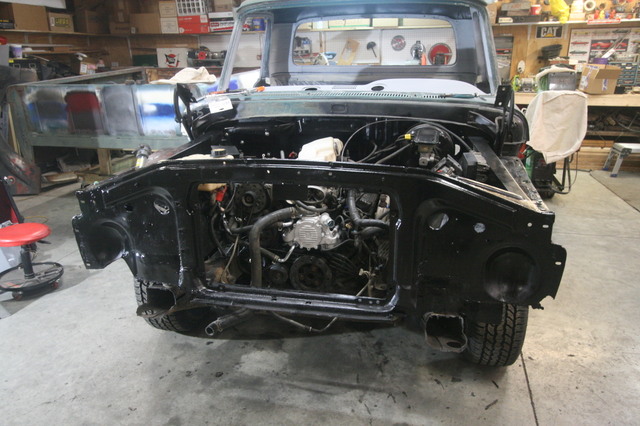
With the radiator support drying I removed the drivers side fender and inner fender after marking the firewall with the inner fender couture and started mocking up the brake booster, I had done a little measuring previously and had a good idea where it was going to wind up, I had to cut the driver side brace that reinforced the firewall for the slicks master cylinder then used the pattern I cut from the RM firewall to mark the location for the RM booster. Then cut that out with the plasma cutter and a step drill for the mounting holes. It just had enough clearance under the cowl and inner fender to fit in a good location.


So with the booster mounted of course I could go inside and check out the brake pedal location....and mock up the steering column.


And the shifter hooked right back up to the linkage and steering shaft, the way it looks like now I won't have to cut the firewall for the column as it's stuck through the slicks original hole in the firewall, the geometry looks good.

We threw the seat in the truck to check it out......not too bad.

More tomorrow....

Jon
-------
Mock up (part 4)
The radiator support or core support has the job of carrying all the weight of the front end sheet metal so it needs to be mounted to the frame securely but also needs a little bit of adjustment for the alignment of all the parts it is supporting. The original slick frame was a lot narrower than the RM so mounting points were going to be in different locations, there are a lot of different ways you could mount the radiator support to the RM frame but in my case since I had to cut out bad metal from the old support and replace that metal it just made sense to reinforce the area right above the RM frame that the radiator support spanned and use that area to mount the support to.
Once again I reused some of the body mounts from the CV as I did before mounting the cab, these mounts are molded rubber with a plastic center and use a steel insert to support the bottom of the mount and provide a tube for the bolt to pass through, I found the proper location in the frame and drilled my holes then cut a couple pieces of 2x2 tube at a 45 degree angle to make the mount that I would weld to the support.
I test fitted everything using multi-able levels to make sure everything was flat and level, then tacked the pieces of 2x2 to the core support.
Then tore it all back apart again and welded the mounts to the core support.
Then reassembled the front end again... this is what the mounts look like, they are on the engine side of the radiator support.
So with the radiator support mocked up I again removed it and gave it a coat of the rust converter and let it dry over night.
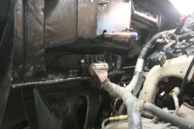
With the radiator support drying I removed the drivers side fender and inner fender after marking the firewall with the inner fender couture and started mocking up the brake booster, I had done a little measuring previously and had a good idea where it was going to wind up, I had to cut the driver side brace that reinforced the firewall for the slicks master cylinder then used the pattern I cut from the RM firewall to mark the location for the RM booster. Then cut that out with the plasma cutter and a step drill for the mounting holes. It just had enough clearance under the cowl and inner fender to fit in a good location.
So with the booster mounted of course I could go inside and check out the brake pedal location....and mock up the steering column.
And the shifter hooked right back up to the linkage and steering shaft, the way it looks like now I won't have to cut the firewall for the column as it's stuck through the slicks original hole in the firewall, the geometry looks good.
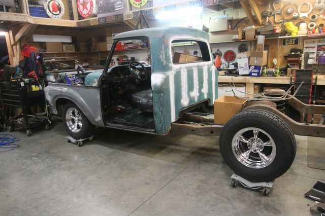
We threw the seat in the truck to check it out......not too bad.
More tomorrow....
Jon