Project instrument panel

A place just for our project & build threads.

Moderators: Casey 65, Kid

User avatar
charliemccraney
Posts: 1743
Joined: July 9, 2008, 10:02 pm
Location: Lawrenceville, GA

Project instrument panel

Post by charliemccraney »

I thought I had already started a topic on this but I can't find it.

This project has been in the works for a couple years now. I've had a lot of other stuff to do and am finally getting back on this.
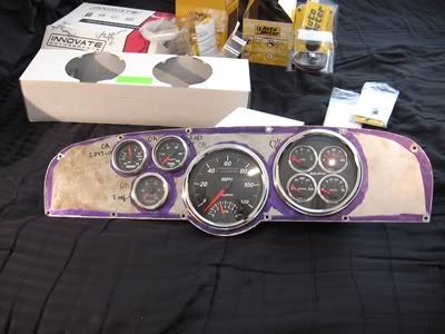
I will be installing a speedo, tach, oil pressure, coolant temp, fuel level, volt, vacuum/boost, fuel pressure, and a/f ratio package with custom indicator lights. The last three gauges are not just for show. I have plans...
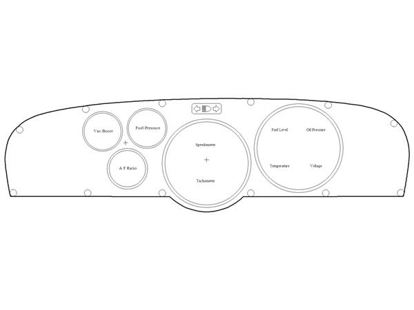
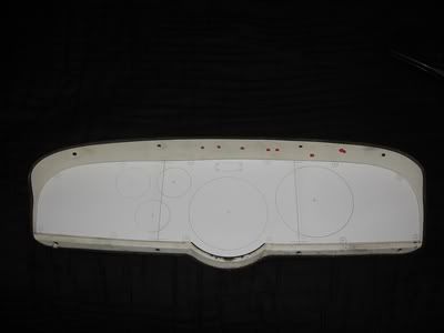
The 2D cad work:

Image

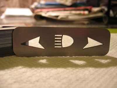
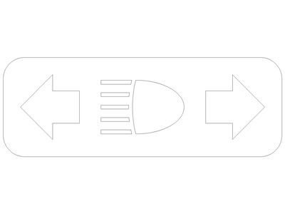
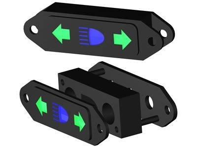
A larger view of the indicator light concept.

Image

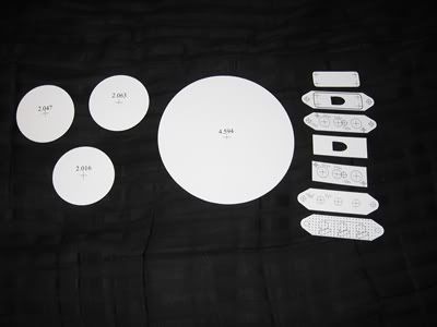
The template, made with 3 pieces of 40lb letter sized paper, taped together.
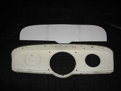
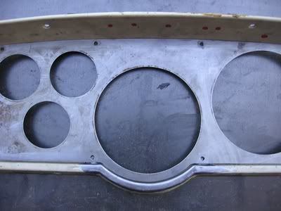
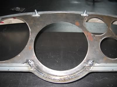
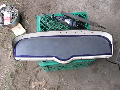
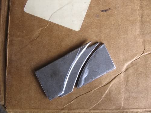
Image Image

And the steel!

Image

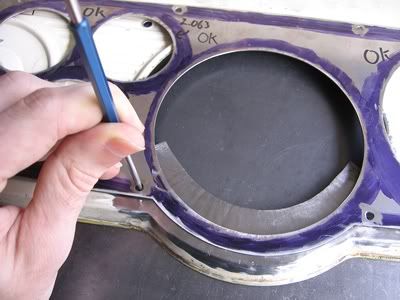
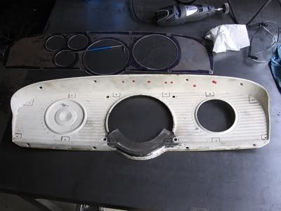
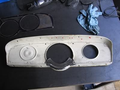
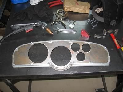
The gauges were fitted in their respective locations. So they will not necessarily fit into another hole, though they are very close in size. Hopefully none of them break.

Image Image

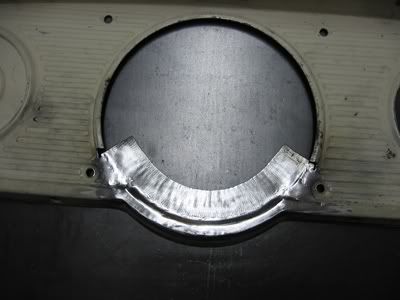
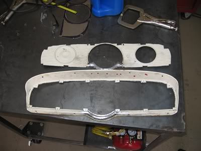
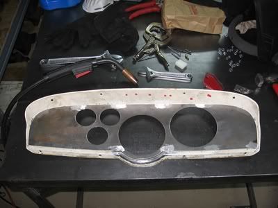
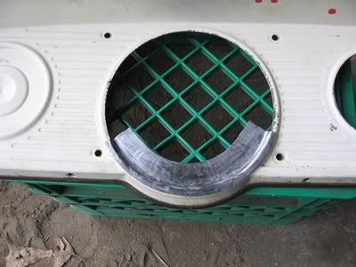
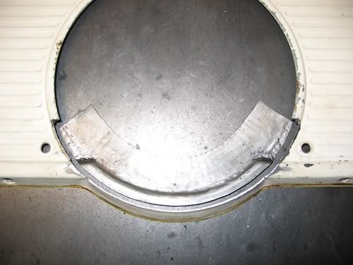
To fit these gauges will require some reworking of a stock panel.
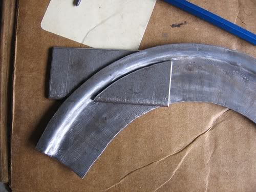
This piece was made using a sheet metal brake for the first bend, some clamps carefully shimmed steel and a hammer for the secong bend, and a shrinker/stretcher to make the curve.

Image

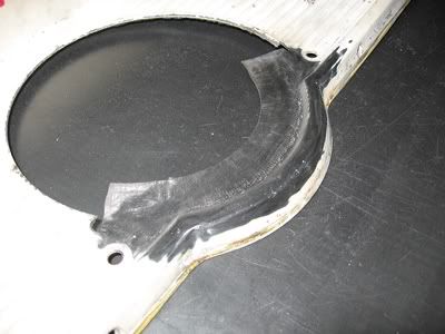
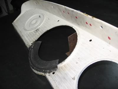
The dies I made to flatten the curved piece where necessary in order to match the instrument panel.

Image Image

Image Image

Image Image

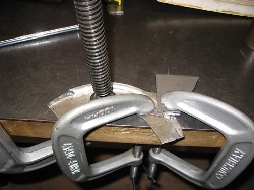
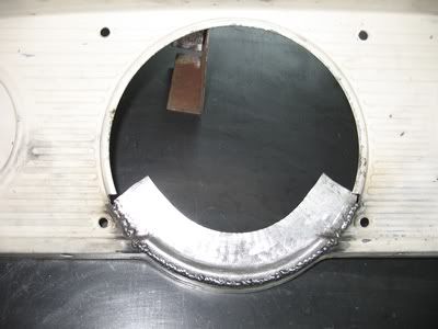
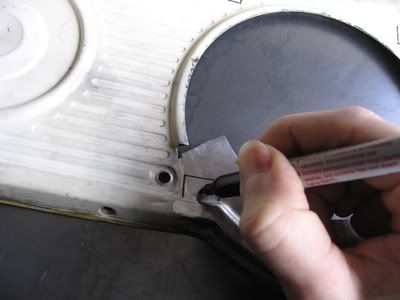
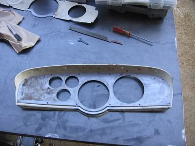
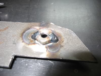
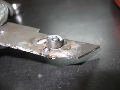
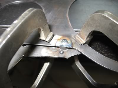
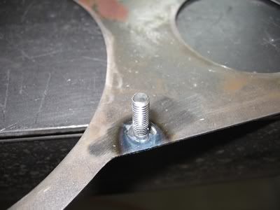
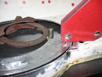
Getting it lined up tor the first tack was tricky. A combination of the panel not being flat, and my novice metal working skills. The solution I came up with is to use magnets to hold it in place and a bolt so that I could use the threads for fine adjustment. The mass of the bolt was not significant enough to stay in place with the force of the piece acting on it so the exhaust clamp prevented the bolt from moving.

Image

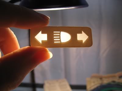
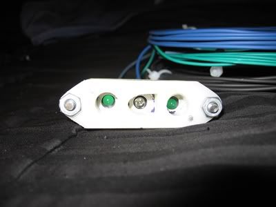
This is the plan for the indicator lights. They will be illuminated with LEDs

Image

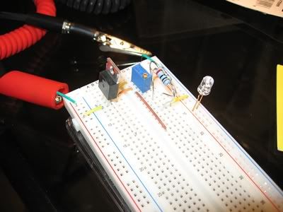
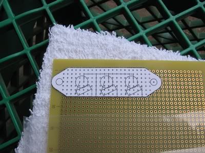
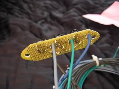
The making of the indicator lights.

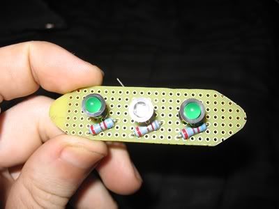
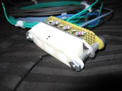
The layout was figured with the help of some cad software. Very convenient. Leds typically require about 3 volts (read your packaging) so resistors are required to drop the voltage from 14.4 volts.

Image Image

Image

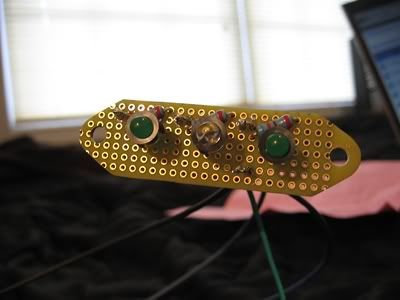
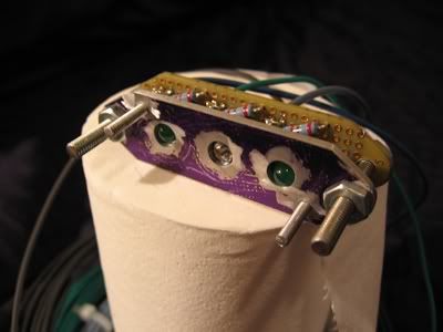
Wires added. It will be plug and play.

Image Image

Image

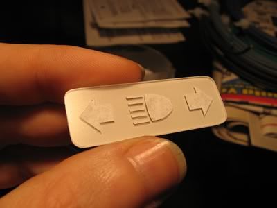
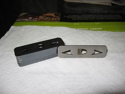
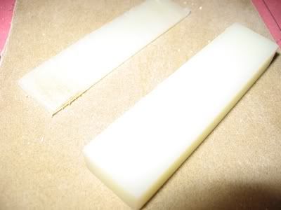
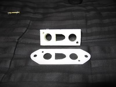
The first (and hopefully last) version of the housing will be made of white nylon. It was cut with a table saw and hand sanded smooth on a flat plate.

Image

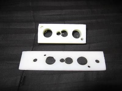
Holes were drilled and then filed where necessary to get the approximate shapes.

Image Image

Image Image

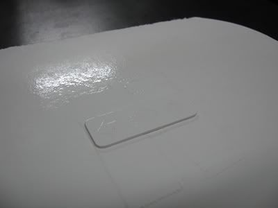
The tricky part will be the lens. This is the way I have determined I will do it but I haven't made it yet.

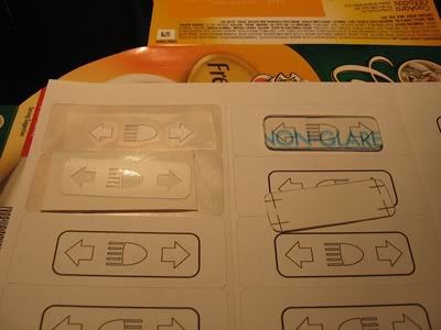
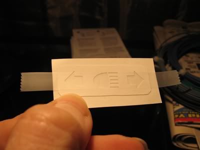
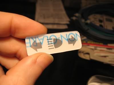
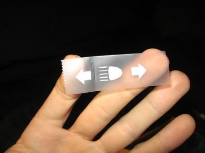
Templates will be printed onto adhesive backed labels. They will then be cut out and carefully positioned. In this first set of pictures, the first sticker you see will be adhesive backed pvc. The intent of this is to help prevent bleeding of the light since the lens will be one continuous piece. The idea is that it will block much of the "stray" light from entering the lens and allow that which is needed to pass through where it is needed.

Image Image

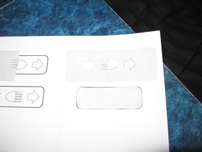
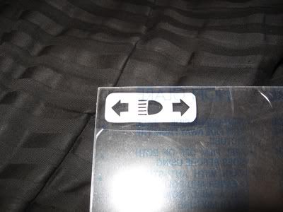
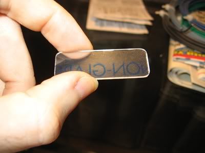
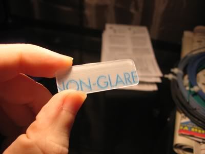
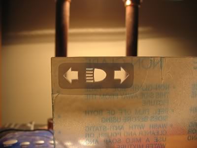
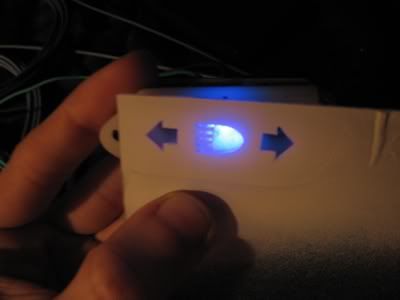
The lens is going to be painted but I don't want to paint over the portion which is for the indicator lights. Rather than placing each piece individually, I came up with a method using scotch tape. I cut them out of the labels with a sharp xacto knife and peel away the unneeded portion. This way they stay exactly where they need to be. Then I gently apply a piece of tape over them and peel them off. Now I can more easily position them to be directly over the piece on the back. Then I carefully cut away the scotch tape and peel what remains off of the label. Because the tape was gently applied, it comes of easily, but is still a little tricky, leaving the label behind to mask off the area I don't want to paint. I did try simply cutting the scotch tape away but for whatever reason I could not get that to work satisfactorily and if it's not mostly cut away, the labels just peel off. With the tape trimmed, the knife can be used to hold down the label and prevent the label from peeling while the tape is removed, when necessary.

Image Image

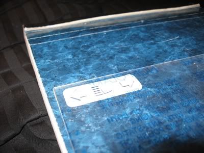
It looks great in person. Soon after these pictures were taken I sanded the back side with 220grit to frost the lens and it looks much better than it did as a clear lens. And, the housing will need to be deeper. The high beam indicator led is too close for how wide the icon is so the round shape of the beam can be seen. I'll get everything installed and functioning as is before I correct that.

Image Image

What's left is to make the final lens, finish preparing the original panel, weld the fastening studs to the insert, paint, and wiring. This project will be finished by summer.
Last edited by charliemccraney on February 22, 2012, 9:47 am, edited 2 times in total.
Lawrenceville, Ga
1961 F100 Unibody
318 Y-block (292 +.070 bore, +.170 stroke), FMS T5-Z w/Mustang 10.5" diaphragm clutch.
napass2004
Posts: 77
Joined: August 7, 2007, 11:00 pm
Location: riverside ca

Re: Project instrument panel

Post by napass2004 »

Wow quite an undertaking pretty creative though looks great keep it up

[ Post made via iPhone ] Image
Gritsngumbo
Posts: 5441
Joined: August 4, 2007, 4:15 pm
Location: Monroe, Louisiana
United States of America

Re: Project instrument panel

Post by Gritsngumbo »

Looking great Charlie. What brand and size gauges are you using (speedo/tach and the large one with fuel/temp/oil/voltage)? Don't think I've seen any that were that large.
If you understand what you’re doing, you’re not learning anything.


LITTLE RED: 64 F100 Short Style
BIG RED: 62 F100 Long Uni
BIG “UN": 63 F250 Long Flare
BBW RED: 61 F100 CC BBW Long Uni
CRIMSON CREW: 63 F100 "Stageway" Long Flare Crew Cab
"RANGER": 66 F100 CC Long Flatbed
"AVA" 1963 Avion T-20 Travel Trailer
“Lucille” 1955 New Moon 44’ Travel Trailer
User avatar
charliemccraney
Posts: 1743
Joined: July 9, 2008, 10:02 pm
Location: Lawrenceville, GA

Re: Project instrument panel

Post by charliemccraney »

All but the a/f gauge are Autometer. The a/f gauge is Innovate Motorsports
The smaller ones are 2 1/16" The Bigger ones are 5"
Last edited by charliemccraney on February 20, 2012, 11:17 pm, edited 2 times in total.
Lawrenceville, Ga
1961 F100 Unibody
318 Y-block (292 +.070 bore, +.170 stroke), FMS T5-Z w/Mustang 10.5" diaphragm clutch.
deflaytedwayz
Posts: 41
Joined: April 10, 2011, 8:48 pm
Location: Antioch, CA
Contact:

Re: Project instrument panel

Post by deflaytedwayz »

Props on the work, but it looks like you'll need a pilots license with all those gauges

[ Post made via Android ] Image
fire truck
Posts: 2141
Joined: January 17, 2010, 9:06 pm
Location: Down in Mississippi and up to no good
United States of America

Re: Project instrument panel

Post by fire truck »

neat
So good lookin' that I've attracted an international stalker.


Rest in Peace Bumpstick....I miss ya man.
User avatar
charliemccraney
Posts: 1743
Joined: July 9, 2008, 10:02 pm
Location: Lawrenceville, GA

Re: Project instrument panel

Post by charliemccraney »

Some more progress.

Ground the welds.

Image Image

Marked the original panel for the cutout.

Image Image

Image Image

Image

Fitted the new insert.

Image Image
Lawrenceville, Ga
1961 F100 Unibody
318 Y-block (292 +.070 bore, +.170 stroke), FMS T5-Z w/Mustang 10.5" diaphragm clutch.
User avatar
slickmainer
Posts: 2555
Joined: October 8, 2007, 6:41 pm
Location: Auburn Maine
Contact:
United States of America

Re: Project instrument panel

Post by slickmainer »

im amazed by the skill that is on this forum. myself not included. shrug.gif im clueless
--Gregg--
you can't get there from here
User avatar
charliemccraney
Posts: 1743
Joined: July 9, 2008, 10:02 pm
Location: Lawrenceville, GA

Re: Project instrument panel

Post by charliemccraney »

Today I was able to drill the holes in the panel and weld the studs onto the insert.

I had to make a tool to hold the studs while they were welded. This is what I cam up with using some scrap. Only as much pressure as is necessary is used with the clamps. It'll bend very easily while welding.

Image Image

Image Image

And this is where I'm at.

Image Image

Image

I'll use some filler to make it look like one piece. This will allow a clean look and make it relatively easy to make upgrades in the future.

I will update my template in "Hints and Tricks" soon. It's good. It's very close but now that I actually have the insert made, it can use some slight adjustments. viewtopic.php?f=5&t=15238
Lawrenceville, Ga
1961 F100 Unibody
318 Y-block (292 +.070 bore, +.170 stroke), FMS T5-Z w/Mustang 10.5" diaphragm clutch.
User avatar
lo6fo
Posts: 86
Joined: January 29, 2012, 10:17 am
Location: omaha, ne
United States of America

Re: Project instrument panel

Post by lo6fo »

im amazed at your creativity. awesome work. cant wait to see the finished product.
64 f100 long bed 292 with a 4 speed
User avatar
Max
Posts: 3456
Joined: July 11, 2006, 11:53 am
Location: 29°35'07.00"N 95°09'07.49"W
Contact:
United States of America

Re: Project instrument panel

Post by Max »

This is cool to watch unfold!
"If you don't want to stand behind our Troops, feel free to stand in front of them."

1964 Ford F100
1967 US Army M416
User avatar
charliemccraney
Posts: 1743
Joined: July 9, 2008, 10:02 pm
Location: Lawrenceville, GA

Re: Project instrument panel

Post by charliemccraney »

Got started on the lens.

Image Image

The lens "frosted" on the back side with 220 grit.

Image

The light blocking film for the back side, made with adhesive backed pvc. This was made by sticking one of the printed labels seen in a picture above onto the pvc and cutting with an xacto knife. The tape over it allowed me to place it precisely.

Image Image

The front masked for painting. This was applied with tape, in a similar fashion to the film above.

Image Image

Hopefully the masks peel off without issue tomorrow. When I was doing my R&D I peeled them off after about 10 minutes. However, I now realize that I cannot just grab it immediately and peel them off. Shoulda thought of that. Oh well. It'll be another problem to solve if it doesn't work.

Success! I nicked it in one spot but managed to touch it up with a bit of paint on tip of a pin.

Image
Lawrenceville, Ga
1961 F100 Unibody
318 Y-block (292 +.070 bore, +.170 stroke), FMS T5-Z w/Mustang 10.5" diaphragm clutch.
User avatar
charliemccraney
Posts: 1743
Joined: July 9, 2008, 10:02 pm
Location: Lawrenceville, GA

Re: Project instrument panel

Post by charliemccraney »

Alright, going a different direction.

Image Image

Now I have to redesign the housing and circuit board and such but this new route will be much easier, even though I had everything made for the other. I'll incorporate a voltage regulator into this new circuit board that will maintain a consistent output voltage for the LEDs so long as there is a reasonable input voltage.
Lawrenceville, Ga
1961 F100 Unibody
318 Y-block (292 +.070 bore, +.170 stroke), FMS T5-Z w/Mustang 10.5" diaphragm clutch.
User avatar
charliemccraney
Posts: 1743
Joined: July 9, 2008, 10:02 pm
Location: Lawrenceville, GA

Re: Project instrument panel

Post by charliemccraney »

I made my test adjustable voltage regulator today. I bought some more hardware to simplify the job, a breadboard. It allows circuits to be set up without soldering.

It was a success.

Image

It works, I swear:


For more info: http://www.rodandcustommagazine.com/tec ... ewall.html

They provide a formula for figuring things out, V = 1.25(1 + (R2 / R1)).

I rearranged it for other stuff. Say you know your target output voltage, V and you've picked out a resistor, R1 and you need to know the resistance required for R2:
R2 = R1(V / 1.25 -1)

And if you know R2 and need R1:
R1 = R2 / (V / 1.25 -1)

This was useful because in my case, R2 is 14.7ohms (R2 is actually 2 resistors, a 10 and 4.7 ohm because the store was out of 15 ohm) and I was able to determine where to set the trimmer, 0 - 500ohm, to avoid damaging the LED with too high a voltage, though the max output voltage as configured is about 5.10volts.

I will probably make two versions of the board, the first with trimmers, that's the blue component with the screw on top. It is an adjustable resistor. Based on what I understand with the specs, it won't be a good idea to use it permanently, but it will allow me to get the brightness dialed in. Once I am satisfied with that, I can measure the resistance and build a board with the appropriate resistor. I'll build a second board rather than simply replacing the trimmers with resistors because I'm sure that adjustability will come in handy for dialing in future projects. The lights and regulator board will be separate components so replacement will be easy.

I didn't really like the green of the old LEDs so I picked a new green but it was super bright so I was worried that it would be too bright. "Warning! Do not stare at LED may injure eyes" is on the packaging. I like the color and I'm happy to see that it has quite a range for the voltage. It's rated at 3.2 volts but there is a faint glow at even 1.4 volts so it won't be too bright. Now that I know which components will be used, I can complete the design of the housing to suit the new symbols and layout.
Lawrenceville, Ga
1961 F100 Unibody
318 Y-block (292 +.070 bore, +.170 stroke), FMS T5-Z w/Mustang 10.5" diaphragm clutch.
donald luster
Posts: 133
Joined: May 19, 2007, 8:49 am

Re: Project instrument panel

Post by donald luster »

Im very impressed. Keep us all informed about any problems and success of this dash.
BiffWilley
Posts: 49
Joined: January 4, 2013, 12:53 pm
Location: Decatur, Illinois
United States of America

Re: Project instrument panel

Post by BiffWilley »

Very impressed with 'outside the box' thinking. Very cool lil winter project! Thanks for sharing and please keep us updated!

Cheers,
Biff
HawaiiKid
Posts: 123
Joined: October 24, 2012, 9:33 pm

Re: Project instrument panel

Post by HawaiiKid »

Very very cool, neat details that many may not notice but make the truck that much more "Custom" :clap:
2003 F150 SVT Lightning-"Bonnie"-Mid 12s Daily Driver

1963 F100 SWB Project-"Lacy"-Crown Vic frame swap in the process!
http://slick60s.com/viewtopic.php?f=32&t=28059
User avatar
charliemccraney
Posts: 1743
Joined: July 9, 2008, 10:02 pm
Location: Lawrenceville, GA

Re: Project instrument panel

Post by charliemccraney »

BiffWilley wrote:Very cool lil winter project!
Haha, I wish. I officially started the gauge project in March of 2009. A significant change of plans occurred early in 2010 which is when most of the design and layout work for the stuff you see took place. I started to make it in 2011. A small design change took place in early 2012. I have got a lot of other stuff done in that same time. I'd like to say that it will be done this year but it hasn't worked the past four! There's really not a whole lot left to do.

The last thing I did was get measurements for the housing and found that the beam angle of the LED's I have is narrower than I'd like and will require a pretty deep housing. I found some wider angle tri color led's, red, blue, and green all in one that I want to use but I haven't bought them yet. Those will be real cool because I might be able to build a controller to monitor sensor voltages and use the red function of the LEDs as a warning indicator. It wouldn't be too specific, just something to get my attention. Or I may be able to use them as a shift light when I'm racing. I do want a shift light but I don't want it to be obvious and that would do the trick.

So next on the agenda is to get those leds, see if I like them, and continue. I think I have any remaining details figured out. I would like to have it done in time for the Norcross Car Show this year but we'll see. As long as nothing major comes up, it should be done.
Lawrenceville, Ga
1961 F100 Unibody
318 Y-block (292 +.070 bore, +.170 stroke), FMS T5-Z w/Mustang 10.5" diaphragm clutch.
BiffWilley
Posts: 49
Joined: January 4, 2013, 12:53 pm
Location: Decatur, Illinois
United States of America

Re: Project instrument panel

Post by BiffWilley »

Wow thats awesome man! Lots of good work and I definitely appreciate your attention to detail!

Thanks for sharing all of this with us.
Biff
User avatar
Uncle Skip
Posts: 4695
Joined: July 15, 2006, 8:30 pm
Location: Pearland, Texas
United States of America

Re: Project instrument panel

Post by Uncle Skip »

I've said it before and I'll say it again.
The ingenuity and craftsmanship on this forum is as good or better than any other group of people on the entire web.
This is my favorite forum of all of them.
To see the ideas you guys come up with and actually put into practice is absolutely amazing.
Charlie, that is awesome.
Nice work.
I'm not arguing with you. I'm just explaining why I'm right.
Pardon me. Does your deaug bite?
Post Reply